
The engineering challenge
A module can match the nominal diagonal and still fail to assemble because the active area, cover lens, adhesive, bezel, FPC bend or mounting geometry differs from the enclosure design.
Identify the layers and their interfaces
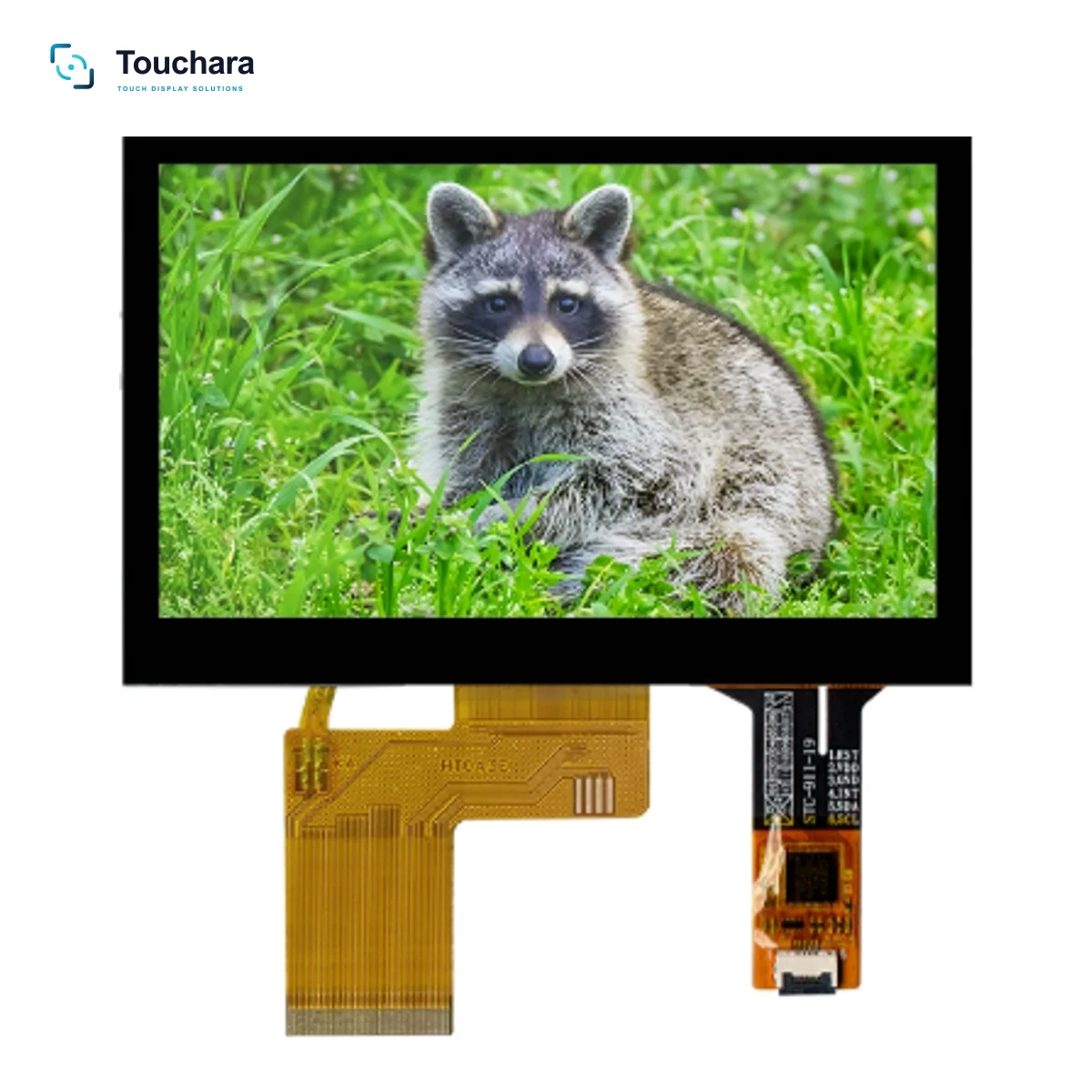
A typical assembly may include a TFT LCD cell and backlight, touch sensor, cover lens, adhesive or bonding layer, touch controller/FPC, frame or bracket and host cable. The exact contents vary by product. Confirm which layers are included in the quote, which are supplied separately and which interfaces are owned by the equipment maker.
At the electrical boundary, record connector series, pin assignment, voltage rails, signal interface, timing, touch protocol, controller firmware and cable length constraints. At the optical boundary, document active area, viewing direction, cover-glass appearance and any printed or coated regions.
Build a drawing-based tolerance stack
Use controlled drawings rather than nominal catalogue dimensions. Check outline, active-area position, sensor and glass thickness, adhesive thickness where specified, frame flatness, mounting points, connector clearance, keep-out zones and cable bend. Combine the tolerances of the display, touch sensor, cover lens, gasket, bracket, chassis and PCB against the available enclosure depth and aperture.
Do not assume a universal ±0.1 mm requirement or a fixed cover-glass hardness. Ask for tolerances and surface properties for the specific feature and test method. Verify touch alignment, viewing-window overlap and assembly access on a representative sample.
Plan assembly and serviceability
Define the assembly sequence, protection of the active surface, cleaning method, adhesive handling, cable routing and replacement procedure. If the module is bonded, state whether the design uses frame/air bonding or optical bonding and whether the supplier or OEM performs the operation. Include inspection criteria for alignment, cosmetic defects, touch operation and image quality.
For serviceable equipment, consider whether the cover lens, touch sensor and LCD can be replaced separately or only as an assembly. The lowest initial BOM may not be the lowest field-service cost.
Parameters to compare
| Layer / boundary | Drawing or specification to check | Integration risk if missed |
|---|---|---|
| LCD and backlight | Active area, thickness, connector, power and optical data | Image position, brightness or host-board incompatibility |
| Touch sensor and FPC | Sensor outline, controller, pinout, cable route | Touch offset, noise or mechanical interference |
| Cover lens and adhesive | Glass outline/thickness, print, surface treatment, bonding method | Aperture mismatch, stack height or visible defects |
| Frame and enclosure | Mounting, flatness, gasket, tolerance stack and access | Stress, gap, poor sealing or difficult service |
Drawing controls for cover glass and mechanical stack-up
Use the released drawing to identify TFT active area, backlight frame, touch sensor, cover lens, adhesive, FPC exit and host connector. A 7H cover-lens hardness target is meaningful only with the stated test method, substrate, coating, conditioning and acceptance rule. Likewise, ±0.1 mm is not a universal assembly tolerance: apply it only to named datums and features where the supplier and enclosure design can hold it.
Dimension the bezel, adhesive land, seal, FPC bend radius and connector access as keep-out zones. Calculate worst-case stack-up from datum-linked tolerances, then inspect first articles in the actual mounting arrangement.
OEM decision framework
Freeze the interface-control drawing before tooling. Record the approved sample revision, any deviations, acceptance criteria and who validates optical, touch, mechanical and environmental behavior. When the supplier’s drawing is incomplete, make the missing features an explicit RFQ action item rather than filling in tolerances by assumption.
RFQ checklist
Include these items with the inquiry so suppliers can quote and validate the same configuration:
- Exploded BOM identifying included and excluded layers
- Controlled outline and interface drawings with revision
- Touch controller, FPC pinout, cable and firmware details
- Bonding method and inspection criteria, if applicable
- Tolerance stack and sample-validation responsibilities
Preparing an OEM display inquiry?
Share the target size, interface, operating conditions, mechanical drawing and expected quantity for a project-specific discussion.