
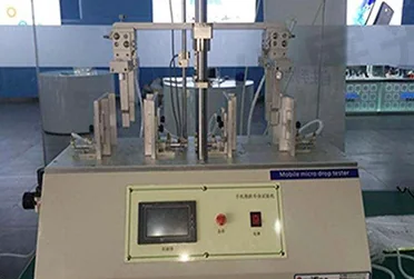
The engineering challenge
Factory equipment exposes displays to vibration, switching noise, dust, oils, cleaning, operator gloves and frequent interaction. These stresses can interact: a mount can loosen, a cable can pick up noise, and touch tuning that works on the bench can become unreliable after installation.
Start with the installation environment
Record vibration sources, mounting orientation, expected shocks, temperature, contamination, cleaning, power quality, cable routes and operator tasks. Define what the display must continue to do during and after each exposure. Select environmental test methods and severities from the equipment specification and the applicable edition of the relevant IEC 60068 methods; a generic vibration test does not reproduce every machine installation.
Design the mechanical and electrical integration together
Check frame stiffness, fasteners, gasket compression, glass support, connector retention and cable strain relief. Review interface timing, grounding, shielding, return paths, filtering and separation from motor or inverter wiring. Verify touch-controller behavior with the host board, power supply, cable length and enclosure present. If the machine contains high-energy switching or variable-speed drives, test in representative operating modes.
EMC immunity and emissions are properties of the assembled equipment and its installation. A display interface or controller feature alone is not evidence that the HMI will pass the machine’s EMC plan.
Make the operator test realistic
Evaluate target size, viewing angle, brightness, status indicators and touch response in the actual lighting and operator position. If gloves, moisture or protective films are involved, specify them in the validation. Measure false activations and missed inputs under the agreed conditions rather than relying on a generic touch-mode label.
Parameters to compare
| Stress | Design checks | Validation record |
|---|---|---|
| Vibration/shock | Mounting, fasteners, cable retention, glass support | Test fixture, installation axes, profile and post-test inspection |
| Electrical noise | Grounding, shielding, cable routing and host power | Operating modes, disturbance setup and observed touch/image behavior |
| Contamination/cleaning | Seal boundary, surface and material compatibility | Specified agent or dust exposure and acceptance criteria |
| Operator use | Viewing conditions, glove, wet touch and target layout | Representative task protocol and results |
Use the installed equipment profile for shock, vibration and EMC
Build the qualification profile from machine location, mounting orientation, resonance, transport loads and operating duty. Specify the test method, axes, frequency range, amplitude, duration, powered state and pass/fail criteria. Inspect connectors, FPC retention, frame and bonding after exposure, then repeat display and touch checks.
For EMC/EMI, name the applicable product or system standard and test configuration. Grounding, shield termination, cable routing, host switching noise and touch-controller tuning must be evaluated in the integrated equipment; a bare module result cannot represent every enclosure.
OEM decision framework
Build a qualification matrix that maps each hazard to a design control, test, acceptance limit and owner. Review deviations after testing and repeat affected tests when a critical component, cable, enclosure or firmware changes. Keep the test configuration identical to the approved production design or document why a difference is acceptable.
RFQ checklist
Include these items with the inquiry so suppliers can quote and validate the same configuration:
- Machine type, mounting orientation and environment profile
- Touch use conditions, including gloves or moisture
- Host interface, cable length and grounding details
- Required vibration, ingress and EMC standards/test configuration
- Drawing revision, sample quantity and acceptance criteria
Standards and references
Check the applicable edition and scope for your equipment before specifying a test or making a compliance claim.
Preparing an OEM display inquiry?
Share the target size, interface, operating conditions, mechanical drawing and expected quantity for a project-specific discussion.