
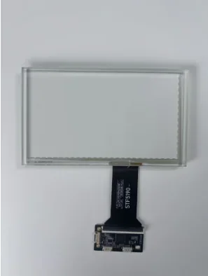
The engineering challenge
A sensor that responds well on an open bench can lose margin after adding thicker glass, printed borders, a long FPC, a noisy power supply or a grounded metal enclosure. Troubleshooting is faster when the sensor design and system conditions are recorded together.
Understand the sensor and cover stack
Projected-capacitive sensors use patterned electrodes to detect changes in capacitance when a conductive object approaches or contacts the cover. Electrode geometry, pitch, routing, panel size and controller channel configuration affect signal level and spatial resolution. Materials such as ITO or metal mesh have different optical, electrical and manufacturing trade-offs; material choice alone does not guarantee the finished behavior.
Record cover-glass thickness, air or bonded stack, printed borders, coatings, FPC length and grounding. These factors affect the signal reaching the controller and should match the production assembly during tuning.
Tune against the host environment
Controller parameters may include scan timing, sensitivity thresholds, filtering, baseline tracking and rejection logic. Tuning should use the actual display, host board, power supply, enclosure, cable, ground strategy and nearby switching sources. Document firmware and configuration revisions. Test intended touch conditions such as bare finger, specified glove, moisture or protective film separately; support for one condition does not prove support for another.
For noise investigation, capture the controller diagnostics and test conditions. Change one variable at a time—power, grounding, cable routing, display mode or shielding—so that the cause and improvement can be reproduced. Avoid reporting a universal noise-immunity figure without an agreed disturbance method and acceptance limit.
Make performance measurable
Define touch accuracy, response time, missed input, false activation, multi-touch behavior and recovery criteria for the user interface. Use repeatable paths and target sizes, and record environmental and electrical conditions. If the equipment is safety-related or used in a regulated setting, coordinate touch acceptance with the system risk and compliance plan.
Parameters to compare
| Design input | Potential effect | What the validation should record |
|---|---|---|
| Electrode geometry | Signal distribution and spatial response | Sensor revision, channel map and target/edge behavior |
| Cover stack | Signal attenuation, optics and mechanical feel | Material, thickness, bonding and tested assembly |
| Controller configuration | Sensitivity, filtering and rejection behavior | IC, firmware, parameter set and tuning revision |
| Host environment | Noise coupling through power, cable and ground | Board, display mode, routing and disturbance conditions |
Connect ITO geometry to measurable touch performance
ITO is a transparent conductive oxide used to form touch-sensor electrodes. Review sensor pitch and pattern, sheet resistance, cover thickness, bezel/ground geometry and controller channel configuration together. Tune thresholds, filtering, scan settings and firmware against the final host’s charger, motor, display and cable noise.
Define touch accuracy, latency, false-touch rate and recovery behavior under dry, wet and gloved conditions as applicable. Record test configuration and raw results so an apparent improvement can be reproduced across units and revisions.
OEM decision framework
Keep a configuration record that ties sensor drawing, controller IC, firmware, parameter set, cover stack and host interface to the approved sample. Re-run affected touch checks when any of these change. If a product needs glove or wet operation, define the supported conditions precisely and verify them on the final mechanical and electrical design.
RFQ checklist
Include these items with the inquiry so suppliers can quote and validate the same configuration:
- Sensor technology, drawing and electrode/channel configuration
- Cover-glass material, thickness, coating and bonding state
- Controller IC, firmware revision and tuning ownership
- Host power, grounding, display interface and cable details
- Touch acceptance tests for the intended user and environment
Preparing an OEM display inquiry?
Share the target size, interface, operating conditions, mechanical drawing and expected quantity for a project-specific discussion.